Neck Geometry using CAD Software
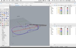
Below you will find a demonstration of drawing a bass neck template using CAD software. Rhino was used to produce this tutorial however the steps shown are not specific to this software. This process works for new making and for replacing necks on existing basses. One could also adapt this process when resetting an existing neck, and you would like to modify the existing neck geometry. By laying out the neck virtually, you can experiment with different parameters and optimize your design before cutting any wood. Once you’re happy with the design, most programs allow you to make a full scale PDF which can be printed by any print shop. Alternatively, templates can be cut out with a CNC router, water jet, or laser using your CAD file.
Before you begin, you need the following information.
-
- Body length
- Mensure length(where the bridge goes)
- Arch height
- Neck mortise angle and depth
- Rib depth and button height
- Fingerboard parameters including edge thickness, total height either end, and length
- Desired overstand including thickness of top at heel
- Desired string length
- Desired bridge Height
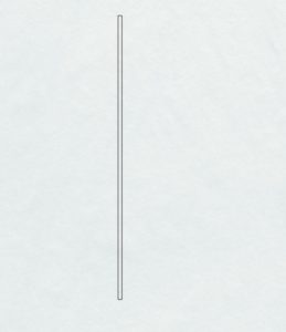 The first step is to lay out the fingerboard. Create a rectangle using the length of the fingerboard(875mm) and height of the edge(12mm)
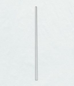
Continue by adding the appropriate height at the nut and bridge end to represent the curved portion. 6mm were added to the nut and 16mm added to the bridge end. Connect both of those lines
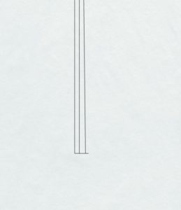 Next, add a 7.5 mm line to the bridge end of the fingerboard. This is an average of the A and D string heights, and it will serve as a reference point for our string path.
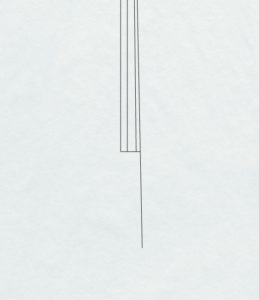 Draw a line the length of your desired string length(105 cm). Start the line at the tip of the nut end of the fingerboard and pass it through the tip of 7.5mm line just drawn.
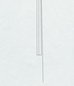 If you’d like, erase the 7.5mm line to keep the drawing from being too cluttered.
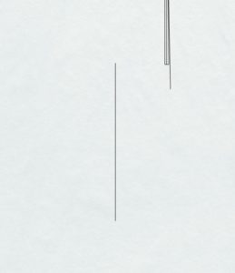 Off to the side, draw a line matching the total length of your top(1114mm)
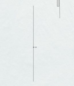 Using your mensure length, mark where the bridge sits and draw a line to represent your arch height(40mm).
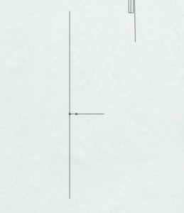 Extend the arch line by the desired bridge height(160mm).
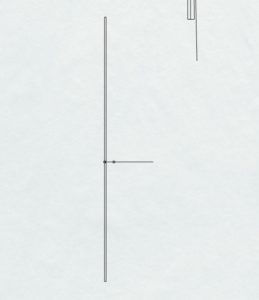 Create a rectangle to the right of your body length line to represent average edge thickness(7mm).
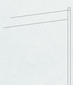 Layout the top of your neck block. This oneis 160mm long and angled down 7.5 degrees. The bottom of the mortise is drawn 25mm below the top of the mortise. Note that the top of the mortise is set in from the end of the top by the amount of edge overhang the bass will have(5mm).
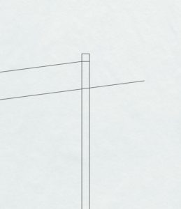 Extend the bottom of the mortise past the edge thickness by your desired overstand. 50mm was used in this example, but 30-40 would be more typical. Use the dimensions you prefer.
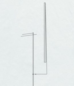 Drag the fingerboard/string length assembly to your bridge.
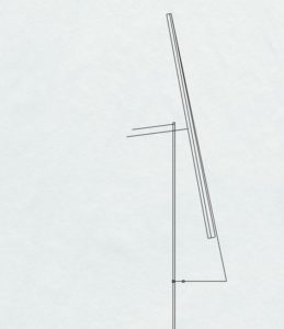 Rotate the assembly until it contacts your overstand line.
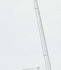 Mark points 50mm in from the nut and 350mm(D note position – 1/3 string length) in from the nut.
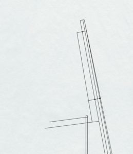 Draw lines from those points equal to your desired neck thickness. This example uses 40mm at the nut end and 48mm at the heel.
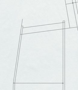 At this point, model the ribs and back. Use rib measurements from the lower block, upper corner, and neck block to create the back/rib plane. Add rectangles to form the edge thickness of the back. Note the back been extended by the desired button height.
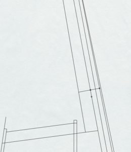 To create a perfect “D neck”, mark a point 16mm past where you previously placed the D.
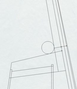 Draw a line from the button to that point, and draw a 25mm radius circle tangent to both lines.
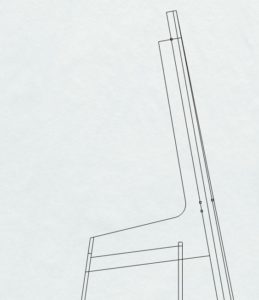 Clean up extra lines. Note that the rib/back plane has been extended the full height of the button as well.
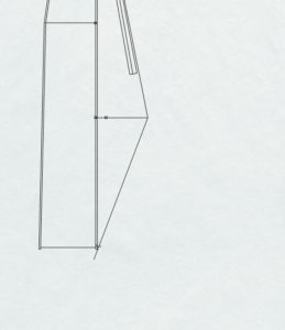 It’s good to check your break over angle. Draw a line that’s 146-148 degrees from the string path.
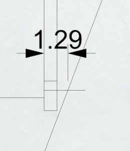 You can determine saddle height and see potential problems. If the saddles needs to be unacceptably high, try modifying either the overstand or the bridge height.
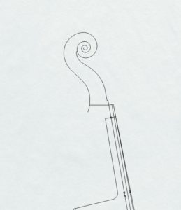 You can stop at this point and make a neck only template. It is possible however to create a full neck template. For demonstration purposes, a scroll will be added to the neck to show how you would model the chin. Start by attaching the scroll to the neck. Rotate the scroll so the nut platform is in alignment with the neck/fingerboard plane.
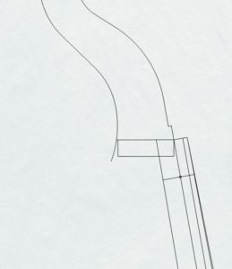 Extend the back of the neck to the cheek and draw a line parallel to the cheek by 22mm.
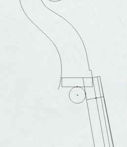 Draw a 20mm radius circle tangent to both lines.
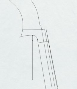 Remove excess lines. In this example, an 18 cm radius connects the previous arc to the chin. Experiment to find a good looking radius for your particular drawing.
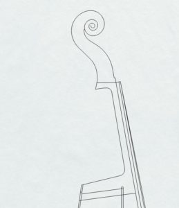 Remove all excess lines to get your completed neck
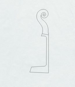
From here, isolate just the neck and use your software to create a full scale PDF.
Brilliant. Thanks for sharing!
Hi Joey,
Very clear and useful.
Have you modeled the plates yet?
Ken McKay